Solar Panels On Sloped, Wood-Framed Roof
by John F Mann, PE
Contents
Evaluation For Downward (Gravity) Loads
Design Loads
Load Distribution
Connector Requirements For Wind Uplift
Rafter Construction
Case Study; Over-Framed Rafters; Lack Of Bracing
Roof framing evaluation should be performed for solar panel installations. Although the weight of panels is very low (3 psf), the investment is relatively large ($70,000 or so for typical house).
Basic explanation for determination of wind uplift force (for design of tiedown connectors) is included under Design Loads.
Evaluation For Downward (Gravity) Loads
The most important issue is to determine if the roof structure is adequate, even without solar panels. This may at first seem unnecessary, especially if the roof has been in place for many years. However, the following potential problems should be considered;
(1) Damage, such as decay for wood framing (or corrosion for steel framing) due to current or past roof leaks. For older houses, decay damage is often found at the base of valley beams. Roof sheathing should be checked carefully.
(2) Inadequate design capacity for design loads (typically per governing building code). Original design may have been flawed, or there may not have been any specific design (especially for older residential buildings). For traditional rafter construction, connection capacity at low ends of rafters may be deficient, as discussed below.
(3) Modifications made that have resulted in defective load capacity. Raising back slope for large dormer generally results in the need for a ridge beam due to low-slope rafters which eliminates necessary resistance to outward thrust (for rafters). Skylights should have doubled rafters on each side.
(4) For nominal "flat" roof; lack of any design for "ponding" failure due to ponded rain water in the event of roof drain blockage.
The solar panel support system must be arranged to ensure that loads from solar panels (including snow on panels and wind uplift) are distributed evenly to roof framing members.
Design Loads
The following design loads must be considered for structural analysis.
(1) Dead Load - This is weight of existing materials (roofing, sheathing) and equipment, including new solar panels.
Uniform dead load for solar panels is calculated as weight of panel (plus weight of rails under panel) divided by area of panel. Typical value is 3 pounds per square foot (psf). However, load from solar panels must be considered point loads (not uniform) since weight of panels is distributed to individual base mounts.
For roof framed with rafters and covered with asphalt shingles, a value of 10 psf uniform dead load pressure for roof materials is often used for design. This weight includes roofing (3 psf), roof sheathing (2.5 psf), insulation (0.5 psf) and allowance for one additional layer of roofing in the future. However, for analysis, actual conditions might allow for lesser dead load or might warrant greater dead load.
Uniform design dead load (PLF) for the rafter is uniform dead load pressure times rafter spacing plus weight of each rafter. For 10 psf uniform dead load pressure, and 16-inch rafter spacing, design dead load (without considering solar panels) is then;
10 psf x (16/12) + 2 PLF (rafter) = 15 PLF (pounds per linear foot).
For a 16-foot long rafter, total dead load (DL), before considering solar panels, is then 240 pounds.
For house built less than 15 years ago, it is likely that there is only one layer of roofing. For a house built more than about 30 years ago, two layers of roofing are much more likely.
For a sloped ceiling, weight of gypsum board (drywall) must be included, typically at 2 psf for 1/2-inch thickness.
HVAC equipment installed in an attic space should be checked to determine if it may be hanging from rafters.
Point load from solar panels depends on details of the support system. For a row of panels (5 feet long) supported by 2 rails, with base mounts spaced at 4 feet (along rail), point load is calculated as;
Solar panel point load = 3 psf x (5 ft / 2) x 4 feet = 30 lbs
Although this point load force may appear very small, consider that 30 pounds is a 12.5 percent increase of total dead load (240 lbs) on a 16-foot long rafter without solar panels. If 6 base mounts (for 3 rows of panels) were to be concentrated on one such rafter, weight of solar panels (180 lbs) would increase dead load by 75 percent. This potential effect becomes even more significant for snow load.
(2) Snow Load - Standard requirements for new construction (per governing building code) should generally be used. When applicable, code provisions for "unbalanced" snow load, drift surcharge and sliding snow must be used.
Snow load applied to solar panels results in point loads on the roof framing, calculated just as for weight of solar panels. These point loads are much greater since uniform snow load is much greater than weight of panels.
Unbalanced snow load provisions will almost always govern analysis of rafters (to support solar panels) for a gable (A-frame) roof.
For a gable roof with horizontal rafter span (ridge to eave) less than 20 feet, unbalanced snow load is equal to Importance Factor (typically 1.0) times the "ground snow load", as defined on the standard snow map in ASCE 7-05 (Figure 7-1) and as modified by any applicable local code. For areas identified as "CS", local code officials should be consulted.
For New Jersey, a larger scale map is available in the UCC (Bulletin 94-8).
For horizontal rafter span greater than 20 feet (ridge to eave), see 7.6.1 of ASCE 7-05 for provisions to determine unbalanced snow load. However, use of ground snow load is conservative.
Drift surcharge (additional snow load) applies for a low roof adjacent to a wall, such as for the roof of a one-story attached garage against wall of a two-story house. Peak total snow pressure can easily be 50 psf, tapering down to the basic uniform pressure over several feet.
Sliding-snow surcharge (additional snow load) applies for a lower roof below the eave of a higher, sloped roof. This condition is applicable for a porch roof below a higher, gable roof that slopes down towards the porch.
Glass surface of solar panels is reasonably considered to be a "slippery" surface that allows for reduction of uniform snow load on a sloped roof. However, it is important to carefully study code provisions for unbalanced snow load. ASCE 7-05 does not allow for reduction of unbalanced snow load for slippery roof surface, when horizontal span of rafters (ridge to eave) is 20 feet or less.
The typical Load Duration Factor of 1.15 for snow load (per NDS) might be increased slightly when considering snow on solar panels since snow tends to melt and slide off panels (see photo below).
For warm-climate areas, where snow load is not significant, basic uniform "Live Load" should be used. However, a reasonable case might be made that such uniform live load can not occur when solar panels are on the roof.
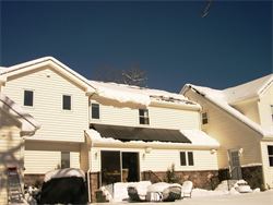
When the sun returns after a snowstorm, snow tends to slide off the glass surface of solar panels, especially since panels are on the south-facing roof slopes. However, during the snowstorm, snow does accumulate on panels.
Holmdel, NJ, day after major snowstorm on Feb 10, 2010. Panels are on high roof (center) and low roof. Snow has accumulated on panels on the high roof. Panels on low roof are already snow-free.
Photo courtesy of MyNJSolar LLC.
http://mynjsolar.com/
(3) Wind Uplift - Standard requirements for new construction (per governing building code) should be used. In general, wind uplift pressures are considered the same when solar panels are installed flat on the roof surface (even with rails). However, any different information from the solar panel manufacturer should be considered.
"Components and cladding" wind pressures are applicable (not MWFRS pressures). For "simplified" design, use Table 6-3 in ASCE 7-05.
For each tiedown connection, "effective wind area" (EWA) is based on "tributary area", per ASCE 7-05 definitions. EWA is calculated as follows;
Case 1 - For 2 rails supporting one row of panels (or outer rail at edge of panel array). EWA is equal to connector spacing (along rail) times half the rail spacing. For this case, EWA will generally be less than 10 square feet. Use 10 square feet in Table 6-3.
Case 2 - For interior rails supporting ends of two rows of panels. For interior rail, EWA is equal to connector spacing (along rail) times rail spacing. EWA might then be close to 20 square feet.
Proper calculation of wind uplift forces must consider the three standard zones, although Zone 3 pressure is usually not relevant.
For a row of panels along ridge or eave, use of Zone 2 pressures will be conservative. Deduct 2 psf (weight of panels) from gross uplift pressure (from Table 6-3).
For a rail-supported panel system (2 rails per row), a conservative calculation of wind uplift force (Fw) on an interior tiedown connector (typically lag screw into rafter) near ridge or eave is determined from;
Fw = wnet x (Lp / 2) x csp
where;
wnet = Net wind uplift pressure (Zone 2 pressure - 2 psf)
Lp = Length of panel (perpendicular to rails)
csp = Spacing of tiedown connector, along rail
For basic wind speed of 100 mph, wind uplift pressure for Zone 2 (edge strips) is as follows;
Zone 2
Roof angle EWA Wind Uplift Pressure
> 7 to 27 degrees 10 sf 28.7 psf
20 sf 26.4 psf
> 27 to 45 degrees 10 sf 21.0 psf
20 sf 20.1 psf
See "Roof Slope Conversion Tables" to convert roof slope angle to the more usual rise / run format.
For gross uplift pressure of 28.7 psf (components and cladding), panel length of 5 feet (on 2 rails) and tiedown spacing of 4 feet, wind uplift force to be resisted by tiedown connector is 267 pounds.
More accurate calculations can be performed considering actual distribution of Zone 2 and Zone 1 pressures on the panel array.
See below for discussion of connector requirements.
If panels are to be installed tilted or slanted with respect to the roof surface, more detailed evaluation of wind effects must be performed.
In general, evaluation of wind uplift capacity for the entire roof is not performed. Cost of any remedial work necessary to increase capacity for code-specified wind uplift pressures would likely be very high. Also, weight of solar panels actually improves uplift capacity assuming gross uplift is the same as existing conditions.
However, for long roof trusses (over 35 feet) in high-windspeed areas (100 mph or greater per code wind map) connections at exterior wall supports should at least be checked to see if light-gage steel tiedown connectors ("hurricane ties") have been installed. If not, the owner should be informed to consider remedial work.
Load Distribution
Careful consideration of load distribution is required for proper analysis.
Solar panels are often supported on "rails", installed perpendicular to (across) or parallel to rafters. Rails are supported by individual mounts (base mounts) that may be spaced at 4 feet or more along the rail. Therefore, load from solar panels, including snow on panels, will be concentrated at the base mounts.
If rail base mounts are not well distributed, individual roof framing members can easily be overloaded, as indicated above by sample calculations. Therefore, either a specific base mount layout plan must be developed, or very conservative assumptions about base mount locations must be used.
Connector Requirements For Wind Uplift
Withdrawal capacity of lag screws is calculated per standard provisions of the governing code (NDS) for wood construction. Key condition is that lag screw must be centered in thickness of a rafter to comply with edge distance limits. Small diameter lag screws are also necessary (not more than 5/16-inch diameter).
Protection against roof leaks is imperative, taking into consideration the expected long life of the system and difficulty of making repairs. Proprietary connection hardware is available that includes protection against water leaks. See separate article for additional discussion.
Alternate methods of connection are of course possible, though more complicated.
Rafter Construction
For a roof framed with traditional rafters, the following key issues should be addressed;
- Resistance to outward thrust force (from rafters)
- Capacity of rafters
- Damage, such as decay or splits. Check high ends (at ridge board) to determine if there may be large gaps.
Outward thrust force from rafters is most often resisted by attic floor (ceiling) joists parallel to the rafters, with rafters connected to side face of attic floor joists. However, rafters are sometimes supported on a flat plate (such as 2x4) across the ends of attic floor joists. Adequate connection to resist outward force must be checked.
Although weight of solar panels is relatively small, outward thrust force will be increased, especially for long roof slope covered entirely with panels.
See "Structural Ridge Beam" for detailed discussion of calculations for outward thrust force at low ends of rafters; Structural Ridge Beam.
If attic floor joists are perpendicular to rafters, a structural ridge beam should most likely have been installed (with proper supports) to support high ends of rafters. Outward thrust force from rafters (at low ends) is then eliminated. Otherwise careful evaluation is required to ensure that resistance to outward thrust force has been provided. Extensive remedial work may be necessary.
Collar ties (also known as rafter ties) are often installed across rafters in an attempt to provide additional (or even primary) resistance to outward thrust force. However, collar ties / rafter ties installed more than about 2 feet above low ends of rafters may not be adequate for primary resistance to outward force. Also, the lower segment of rafter (below collar tie) must be checked carefully for bending moment and lateral movement potential.
If there are no attic floor joists at all (for sloped ceilings), there must be a structural ridge beam. However, amazingly, houses (and especially additions) have been built without attic floor joists or a specific structural ridge beam. The roof may have survived without substantial movement for various reasons. However, such roof should not be used to support solar panels without extensive remedial work.
When rafters are determined to be undersized, a short support wall inside attic space is one relatively easy method to provide additional support. The short ("knee") wall must be supported by attic floor joists. Roof load will then be shared by rafters and attic floor joists. Adequate support for attic floor joists must also be available, typically from walls below.
Hip and valley beams should be evaluated carefully. In general, hip and valley beams have not been correctly designed. Supports are typically missing. Considering the relative ease of installation, proper supports should be provided. New posts can usually be supported on a wood plate across attic floor joists.
Case Study
Over-Framed Rafters; Lack of Bracing
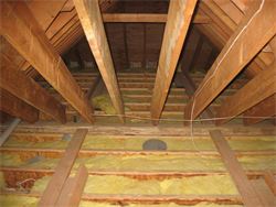
In May 2009, long rafters for a large two-story house in Holmdel NJ were found to be defective during inspection (see photo). Rafters of an upper (over-framed) gable roof are supported on long rafters of an separate gable roof. Roof sheathing was not installed on the long rafters. Also, low ends of the long rafters were not braced. The result was noticeable twisting of the long rafters.
For the long rafters, a structural ridge beam is necessary since attic floor / ceiling joists are perpendicular to long rafters. The 1-3/4 inch thick LVL ridge beam (supporting high ends of long rafters) did not have adequate support. Spacing of slender columns was excessive. Half of one built-up column split and fell away.
These types of defects, which are seen all-too-often with relatively new construction, should be corrected before solar panels are installed.
Long rafters (right) are twisted due to lack of proper bracing. These long rafters support over-framed rafters that support solar panels. Note that attic floor joists are perpendicular to long rafters, so that structural ridge beam is necessary.